Search by code, controller, status and symptom

Audi Fault Code Index and Diagnostic Guide

An Audi fault code records a condition seen by one control unit. It does not automatically name the failed part. Use this index to understand the code family, preserve the event data, choose the correct child guide and decide what evidence is needed before a repair is approved.

Send the Complete Scan Details
Controller 01 Engine Code P0299 or VAG event Status static or intermittent Frequency and mileage Freeze-frame and symptom
Quick answer

Search the exact code together with the control module and vehicle details. Save its status, frequency, mileage and freeze-frame before clearing it. Then confirm the cause with circuit, pressure, leak, mechanical, software or road testing. A description such as “signal too low,” “implausible,” “no communication” or “underboost” identifies a test direction, not a shopping list.

Safety before code research

The warning and vehicle behavior decide whether testing can continue

Stop and arrange recovery

Do not continue for a red oil-pressure or overheating instruction, smoke, fuel odor, severe coolant or fluid loss, loud knocking, unsafe braking or steering, damaged tires, repeated shutdown, high-voltage impact damage or a critical electrical isolation warning. Do not keep restarting the car to see whether the code returns.

Reduce load and call first

If a yellow warning is combined with misfiring, reduced propulsion, rough shifting, unstable voltage, a ride-height collapse or repeated charging failure, avoid hard acceleration and long journeys. Park safely and ask whether a controlled workshop trip or recovery is appropriate.

Book diagnosis promptly

A stable yellow warning with normal steering and braking may permit a cautious next step according to the exact owner’s manual message. Avoid demanding driving and preserve the first event. No general index can declare a vehicle safe before inspection.

Code record anatomy

Five fields make the same code more useful

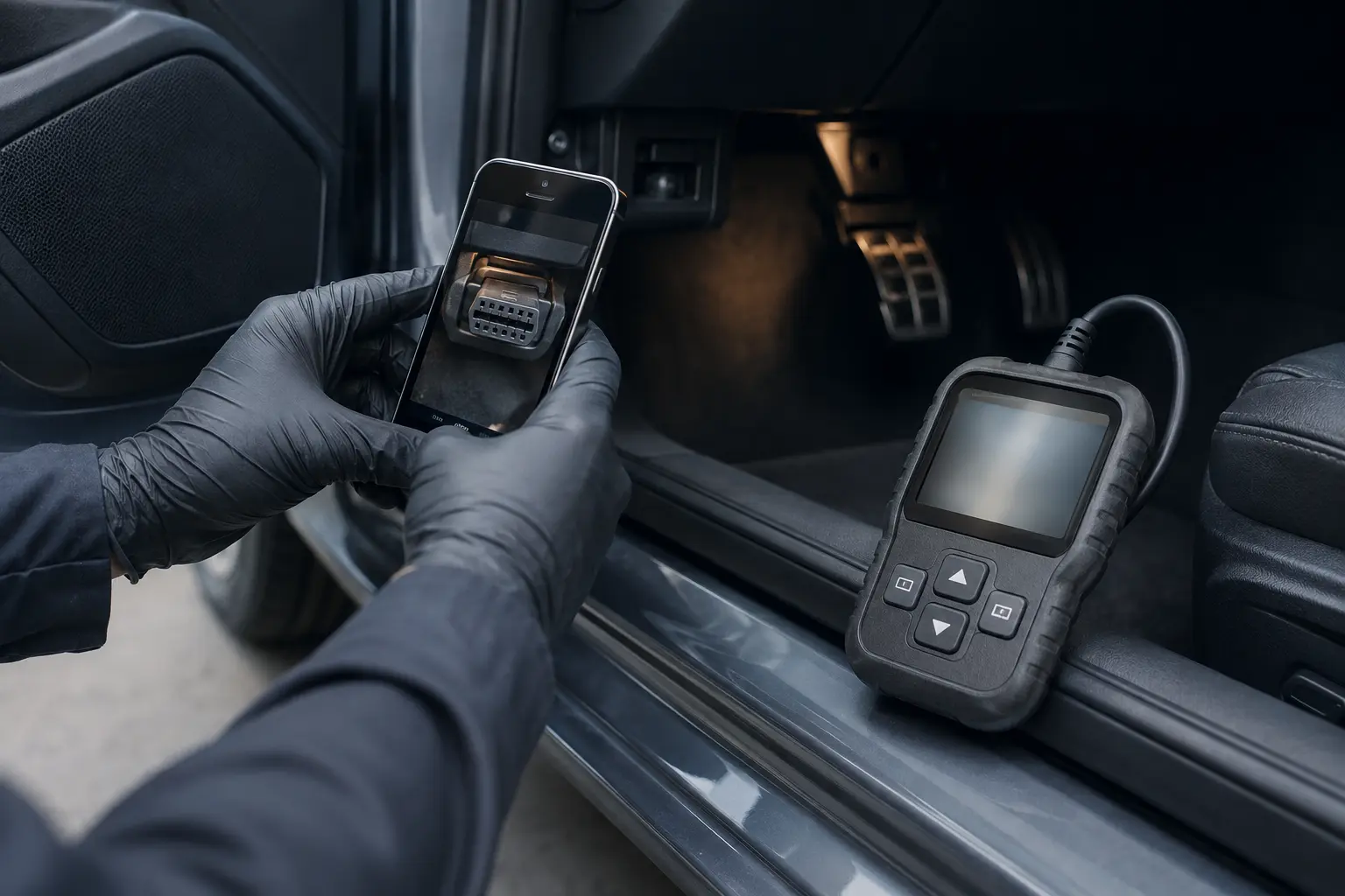
Recording Audi diagnostic connector evidence before testing
Illustrative evidence capture. Save the complete code wording, controller and event data before clearing fault memory.

A bare code copied from a small reader leaves out the context that separates a temporary consequence from a current fault. Ask for the complete report and keep these fields together.

Control module Engine, transmission, ABS, steering, gateway, battery, climate and body controllers can use different descriptions or event formats.
Exact identifier Record the letter and number code, any Audi or Volkswagen event number and the text shown by the scan tool without paraphrasing.
Fault status Static, active, intermittent, sporadic, passive and stored states change the test priority. Note whether the fault returns immediately.
Event data Frequency, mileage, voltage, speed, load, temperature and operating state can reveal the first system that changed.
Driver symptom Cold start, hot restart, boost demand, braking, steering, charging, rain, washing or parked time tells the technician how to reproduce it.

The VIN, production date, engine, gearbox, market and installed options also matter. Audi can use different hardware and software within one model name. A code description from a different engine or generation can lead the test away from the actual circuit.

Generic and manufacturer information

P, B, C and U families are only the first layer

Code familyTypical system areaWhat the letter does not proveUseful companion evidence
P powertrainEngine, emissions, fuel, ignition, boost and transmissionA P code does not prove the named sensor, turbocharger, injector, clutch or catalyst has failed.Freeze-frame, measured values, pressure or smoke tests, wiring checks, combustion evidence and road data
B bodyClimate, lighting, doors, seats, restraints and convenience equipmentA body code does not show whether the problem is the component, switch, wiring, coding or installed-equipment mismatch.Vehicle equipment list, circuit diagram, command and feedback, loaded power and ground, and physical inspection
C chassisABS, steering, suspension, level control and parking brakeA chassis code does not prove the car is safe to drive or that a wheel-speed sensor or compressor needs replacement.Ride height, wheel and tire condition, hydraulic or air pressure, sensor plausibility, geometry and calibration
U networkCommunication between control units and gateways“No communication” does not prove the missing module is defective. It may lack power, ground or network access.System voltage history, network topology, connector and water inspection, wake-up behavior and module supply tests
Audi or VAG eventManufacturer-specific monitoring inside any vehicle systemA translated event name from an unrelated model or old database may not match the installed software.Correct service information, controller identification, software version, event status and guided measurements

Some readers display only generic emissions codes. An Audi-capable scan can access more controllers and richer status data, but tool access alone is not proof. The test plan still needs wiring information, expected values and physical measurements for the exact vehicle.

Audi advises owners to use the vehicle-specific warning information in the official Audi Middle East owners and aftersales information. That warning instruction should sit beside the scan data, especially when the dashboard tells the driver to stop or limit vehicle use.

Common generic OBD code directory

Use the code as an entry point, then verify the scan-tool wording

The entries below are common generic OBD-II labels seen across many vehicles, including some Audis. They are not a list of Audi-specific failures and they do not override the complete description shown by the diagnostic tool. Manufacturer-specific VAG event codes, controller subcodes and symptom bytes need their own application data. “Bank 1” and sensor letters must be mapped to the installed engine before testing.

P00–P03Timing, airflow and position plausibility
P0011Intake cam timing over-advanced

Verify bank and cam designation, oil condition and pressure, command versus actual angle, actuator circuit and mechanical timing.

P0016Crankshaft and camshaft correlation

Preserve startup data. Check sensor signals, timing adaptation and mechanical alignment before replacing a sensor.

P0101Mass-airflow range or performance

Compare measured airflow with load, boost, temperature and engine speed. Inspect unmetered air and contamination.

P0341Camshaft position range or performance

Check the complete label, wiring, reference pattern, oil-related timing control and mechanical correlation.

P0507Idle speed higher than expected

Look for intake leaks, throttle adaptation, crankcase ventilation faults and operating conditions that raise commanded idle.

P2279Intake-air system leak

Use smoke or pressure testing as appropriate. Inspect crankcase ventilation and manifold paths instead of guessing from sound.

P00–P03Fuel pressure, mixture and combustion
P0087Fuel rail or system pressure too low

Compare requested and actual pressure under controlled load, then test supply, regulation, leakage and electrical control safely.

P0171System too lean on bank 1

Review fuel trims by operating range. Check intake leaks, fuel delivery, exhaust leaks and measurement accuracy.

P0300Random or multiple-cylinder misfire

Use per-cylinder counts, load, temperature and fuel data. Do not replace every coil without isolating the pattern.

P0301Cylinder 1 misfire detected

Confirm cylinder numbering for the engine, then separate ignition, injector, compression, mixture and wiring causes.

P0302Cylinder 2 misfire detected

Compare with neighboring cylinders and move components only within a controlled test that preserves evidence.

P0303Cylinder 3 misfire detected

Check whether the event is cold, hot, idle or load related before choosing electrical or mechanical tests.

P0304Cylinder 4 misfire detected

Use freeze-frame, misfire counters and plug condition together. Cylinder-specific does not mean coil-specific.

P2293Fuel-pressure regulator performance

Verify the exact regulator designation and engine application, then compare pressure command, supply and control behavior.

P02–P21Boost, emissions, cooling and runner control
P0234Turbocharger overboost condition

Log specified versus actual boost and control duty. Check actuator movement, control plumbing, sensor plausibility and software context.

P0299Turbocharger underboost condition

Pressure-test the charge path and verify wastegate or actuator control, exhaust energy, sensor accuracy and requested load.

P0420Catalyst efficiency below threshold on bank 1

First exclude misfire, mixture, oil consumption, exhaust leaks and sensor faults. The code alone does not condemn the catalyst.

P0456Very small evaporative-emissions leak

Test the sealed system and cap path using the correct procedure. Ambient conditions and valve sealing matter.

P2004Intake-manifold runner stuck open on bank 1

Verify linkage, actuator command, position feedback, deposits and manifold application before selecting parts.

P2006Intake-manifold runner stuck closed on bank 1

Compare commanded and actual position, check mechanical travel and verify the bank named by the complete code.

P2015Intake-runner position range or performance on bank 1

Check end stops, linkage wear, sensor signal and adaptation. A limit fault needs measurement, not a universal repair.

P2181Cooling-system performance

Compare coolant temperature rise, thermostat control, circulation, fans, sensor plausibility and actual overheating evidence.

P05 and USupply voltage and controller communication
P0562System voltage low

Test battery condition, charging output, grounds and voltage drop. Note whether the event occurred during cranking.

U0100Lost communication with engine controller

Identify which controller reported the loss and when. Test power, ground and network integrity before replacing a module.

U0101Lost communication with transmission controller

Check shared supply or network events, gateway history and whether the fault is static or a low-voltage memory.

U0121Lost communication with ABS controller

Because several systems use wheel and stability data, one network loss can create many dashboard messages.

U0146Lost communication with gateway A

Verify the scan-tool definition and vehicle topology. A gateway event can make multiple controllers appear unavailable.

U0151Lost communication with restraint controller

Treat restraint warnings seriously. Check supply, network and repair history using appropriate safety procedures.

ControllerWhich module stored it?
StatusStatic, intermittent or passive?
EventWhat mileage and temperature?
SymptomWhat did the driver observe?
SequenceWhich code appeared first?
Codes beginning with P1, B, C or many U values may use manufacturer-specific meanings. Search the complete Audi or VAG event text, controller address and symptom information. Do not apply a generic web description to a manufacturer-specific code because the same digits can lead to a different test plan.
From report to repair

Use the code sequence to find the first fault, not the longest list

Identifying an Audi electrical connector before circuit testing
Illustrative circuit-location check. Confirm the actual component and connector before deciding what to test.

Confirm the vehicle and complaint

Decode the VIN and record the model, year, engine, gearbox, market, options, mileage, modifications, recent repairs and exact driver concern. Note whether the event is cold, hot, wet, load-related or intermittent.

Stabilize the electrical supply

Test the 12-volt battery and major connections when voltage or communication codes are present. Use approved support during extended scanning or programming. Low supply can create secondary faults in otherwise healthy controllers.

Scan every relevant controller once

Save the original report before clearing anything. Compare timestamps, mileage, frequency and status. Several modules reporting one voltage or communication event can point toward a shared cause.

Group primary and consequence faults

A failed sensor supply can trigger codes in multiple dependent systems. A boost leak can produce underboost, mixture and airflow plausibility faults. Build a relationship map instead of pricing every line.

Test the supported circuit or system

Choose loaded voltage-drop, pressure, flow, leak, smoke, temperature, mechanical, command-and-feedback or road testing from the code definition and vehicle architecture. Record both expected and measured results.

Repair only the proven boundary

State the failed component or circuit, why it failed when known, required related work, parts route, coding or calibration, and what remains unproven. Obtain approval before widening the scope.

Repeat the original trigger

After repair, reproduce the condition safely, rescan the connected controllers and confirm that adaptations, monitors or basic settings complete as required. A cleared dashboard is not final verification.

What code wording actually changes

Signal, plausibility and communication faults need different proof

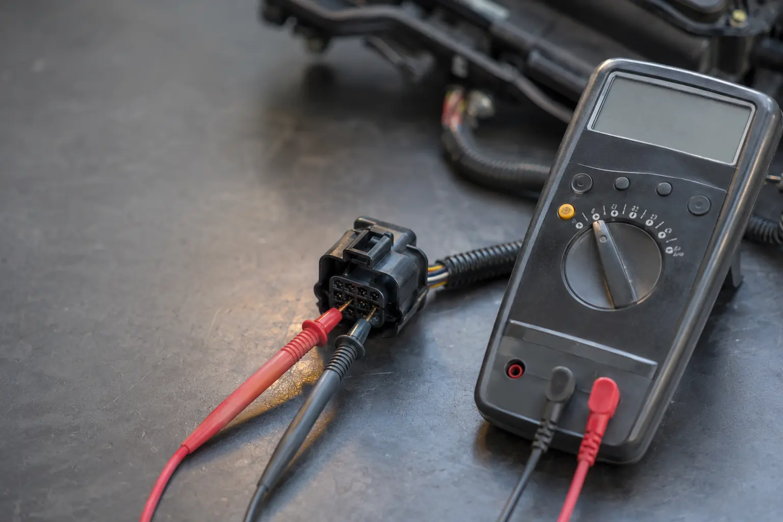
Testing an Audi electrical connector with a multimeter
Illustrative confirmatory test. A code is a starting clue, not proof that a part has failed.

Open, short and signal-level descriptions

These can point toward wiring, connector tension, reference voltage, ground, supply or the component itself. A continuity beep without load may miss resistance that appears when a motor, heater or solenoid operates.

Implausible or correlation descriptions

The value may be electrically present but disagree with another sensor or the expected operating model. Compare related signals, mechanical timing, pressure and temperature before replacing the reporting sensor.

Performance or range descriptions

Underboost, flow, efficiency and regulation codes describe a system that could not achieve a target. Leaks, restrictions, actuator control, wear, software and measurement errors can create the same result.

No communication descriptions

Confirm that the controller exists on the exact specification. Then test its power, grounds, network wires and shared gateway path. A missing unit can be a victim of another network fault.

Do not clear codes before these details are saved

  • Full controller name and identification
  • Exact code or event number and wording
  • Static, active, intermittent or stored status
  • Frequency, mileage and time information
  • Voltage, temperature, speed and load data
  • Warnings photographed in the cluster
  • Conditions that caused or cleared the symptom
  • Recent battery, repair, coding or software work

Clearing codes can remove the timing relationship that makes an intermittent fault affordable to diagnose. Disconnecting the battery may also introduce new initialization work.

Common code clusters

Related faults often share one physical cause

Cluster seen in reportPossible shared directionTests before parts
Low-voltage faults across gateway, ABS, steering and infotainmentDischarged or weak battery, charging issue, high-resistance connection, ground fault or key-off drainBattery capacity, charging behavior, loaded voltage drop, sleep-current pattern and event timing
Underboost with airflow or mixture deviationsCharge-air leak, wastegate or actuator issue, diverter or PCV fault, restriction, sensor error or turbo conditionVisual inspection, smoke or pressure test, actuator command, boost log and related sensor plausibility
Misfire with fuel trim and catalyst warningsIgnition, injector, fuel pressure, air leak, compression, timing or exhaust consequenceCylinder pattern, plug and coil evidence, fuel pressure, injector behavior, leak and mechanical testing
Wheel-speed, steering and driver-assistance warningsTire mismatch, sensor or bearing signal, wiring, voltage, geometry, calibration or impact damageTire and wheel measurement, live wheel speeds, wiring, bearing inspection, alignment and calibration prerequisites
Coolant regulation with temperature or protection faultsLow level, leak, pump, thermostat, valve, fan, restriction, air pocket or sensor disagreementCold level, pressure test, temperature comparison, commanded circulation, fan operation and safe road data
High-voltage or charging events with 12-volt faultsLow-voltage wake-up problem, communication, inlet or cable, thermal limit, isolation issue or charging hardwareHazard assessment, complete scan, 12-volt support, charging-session data, cooling information and qualified HV tests
Repair approval

A defensible estimate connects each item to evidence

The estimate should name the affected system, the test that confirmed the fault and the repair boundary. If the workshop recommends a module, ask whether power, ground, communication, wiring and software state were checked. If it recommends a turbocharger, pump or gearbox, ask for the pressure, movement, leakage, temperature or mechanical evidence that excludes outside causes.

Separate diagnosis from repair, maintenance from active faults, and required work from monitoring. Coding, parameterization, adaptation, component protection, alignment or driver-assistance calibration should be listed when relevant. The final handover should include the original and final scan status plus the test used to reproduce the complaint.

What a scan cannot prove alone

Do not treat fault memory as a physical inspection

  • A code cannot measure pad or disc thickness.
  • A code cannot confirm tire damage, wheel runout or structural condition.
  • A code cannot show every air, coolant, fuel or exhaust leak.
  • A code cannot prove battery capacity from resting voltage alone.
  • A code cannot identify all connector corrosion or water paths.
  • A code cannot confirm that a noise comes from the named system.
  • A code cannot replace a post-repair road, leak, pressure or sleep test.
Using this index correctly

Search with enough detail to avoid the wrong vehicle answer

Use a search such as “2019 Audi Q7 3.0 TFSI P0299 engine control module static underboost after warm acceleration,” not only “Audi P0299.” Add the controller, generation, engine, transmission and event condition. When the scan shows an Audi or Volkswagen number, include that exact identifier and the tool’s full wording.

Do not copy a repair from a forum or video without confirming that the vehicle shares the same engine code, hardware revision and software. A useful case can suggest a test. It cannot prove the same part failed on your car.

For professional information, Audi’s official repair portal can be searched by model year, model and vehicle identification. Use current vehicle-specific wiring, locations, specifications and test procedures. The index on this page is a routing tool, not a substitute for licensed service information or qualified high-voltage work.

Reading order

Start with the earliest shared event in a long report

Sort the report by mileage, time and fault frequency when the scan tool allows it. Look for the first event shared by several controllers, then compare which modules only reacted afterward. For example, a supply-voltage drop may be recorded first, followed by steering, ABS, transmission and infotainment communication faults. That order supports a power test before four unrelated module estimates. A different report may show one boost-control event first and mixture or misfire consequences later.

Status also changes the order. A static safety-related fault deserves attention before an old intermittent convenience fault. A high-frequency event at the current mileage is usually more relevant than a single historical entry from before a battery replacement. Keep the historical code when it explains the story, but do not let it outweigh current measurements. The report should state why each fault was prioritized, monitored or excluded.

Compare the repaired vehicle with that same baseline. If the original event occurred during a hot restart, highway boost demand, overnight parking or a charging session, the verification should address that condition safely. Save the final scan and explain any historical faults that remain stored for monitoring. This makes the handover understandable to another technician and prevents an unrelated old entry from being sold as a new repair.

Continue with the evidence

Connect the code to the warning, symptom and live data

Audi diagnostic verification before a controlled road check
Illustrative final verification. Recheck the original trigger and recorded behavior after corrective work.

Use the code directory to classify the event, then move to the page that holds the next part of the evidence. These hubs are complementary and should not be treated as competing diagnoses.

Fault code questions

Audi fault code FAQs

Does one Audi code identify the failed part?

No. It identifies a monitored condition in one controller. The status, event data, wiring, physical measurements and related faults determine whether the cause is the component, its circuit or another system.

Why do several warnings appear after a weak battery?

Controllers can reset or record low-voltage and communication faults during one supply event. Test battery capacity, connections, charging and the reason for discharge before replacing the modules that reported the event.

Should codes be cleared to see which ones return?

Only after the original report and useful freeze-frame information are saved. Immediate return can be useful, but premature clearing may remove the timing and operating condition needed to diagnose an intermittent problem.

Can a generic OBD reader scan every Audi system?

Usually not. Generic readers often focus on emissions-related powertrain data. Audi-capable equipment can access more systems, though electrical and mechanical tests are still required to prove the cause.

What should I send before booking diagnosis?

Send the VIN, model, year, mileage, full controller name, exact code, status, warning photo, symptom, recent work and whether the vehicle currently has safe steering, braking and tire condition.

Preserve the first event

Call with the controller and complete code wording

The exact report helps decide whether the appointment needs electrical support, pressure testing, a road-data session, high-voltage precautions or recovery.

Call About the Fault Code
Cost guide

What Audi fault-code diagnosis can cost in Dubai

These market ranges cover investigation stages, not automatic parts replacement. A stored code needs the correct test path before a repair price is meaningful.

Service or repairTypical Dubai market rangeConfirm in the estimate
Full scan and fault reviewAED 150 to AED 500Stored data, system direction and initial checks
Electrical or network testingAED 500 to AED 1,500Power, ground, wiring and communication evidence
Coding, basic setting or adaptationAED 250 to AED 800Supported setup after the cause and repair route are confirmed